First Mechanism Design and Test
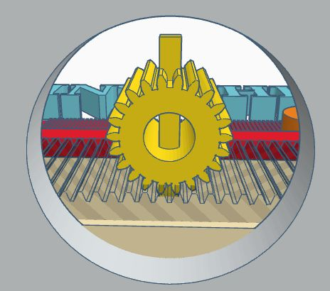
My view is that you have not designed a thing until it has been tested, and it works.
One of the common features of successful bespoke pinball machines is that everything looks over engineered. I suspect the machines built with anything less break; a lot. And this would be very discouraging.
I need to make a few mechanisms. I started designing them with the hardware used in CNC machines and 3D printers. These were heavy and expensive, but very strong. I have seen lots of 3D printed stationary parts on bespoke machines, and the occasional simple mechanism. I decided to try 3D filament printing my mechanisms. Design requirements:
| Requirement | Solution | Notes |
|---|---|---|
| Strong filament | PET | It works in drink bottles… |
| Needs to be strong | (1) Set a minimum thickness of 4mm, and make the insides dense. | A dense infill is stronger than a solid print |
| (2) Give everything the “snap” test. | If I can snap it in my fingers then it stands a chance. | |
| (3) Remove sharp corners. | Sharp angles can introduce distortion. | |
| 3Rs | Recycled packaging. Recyclable waste. |
Proof of Concept Design
The first this to test if the lifting potential of a mechanism printed with my tools and equipment.
I’ll need a 3D design and some Stepper Motors. Oh and a CNC controller, some stepper control modules, a power supply, a lump of wood and some screws and stuff.
Stepper Motors
I got a Box of Stepper Motors:
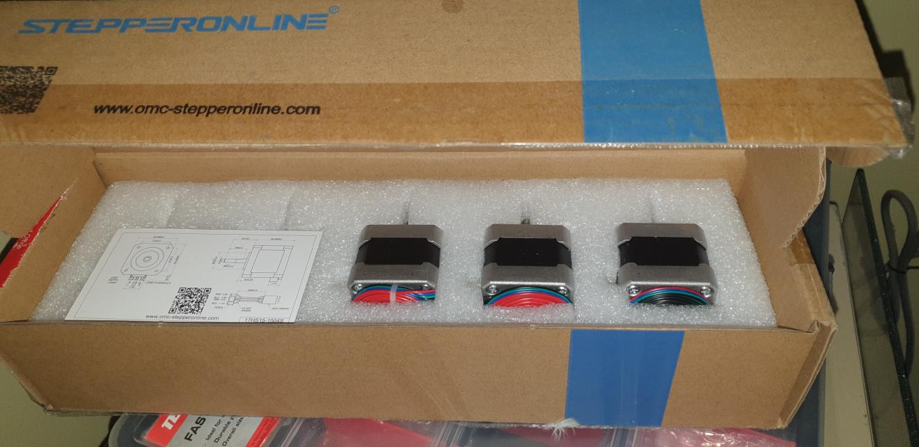
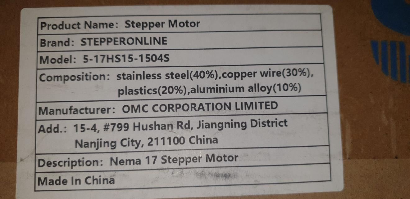
CNC controller
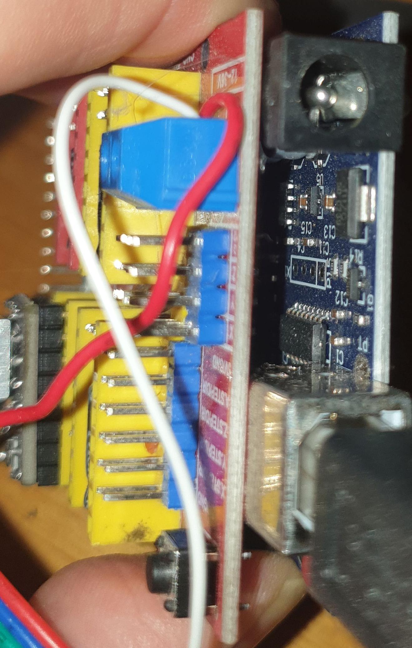
The CNC Controller is quite generic.
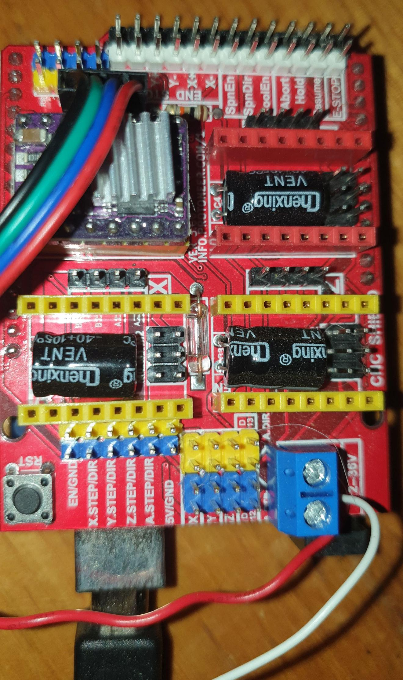
It has a microcontroller board underneath, a standard Arduino clone.
Stepper Modules
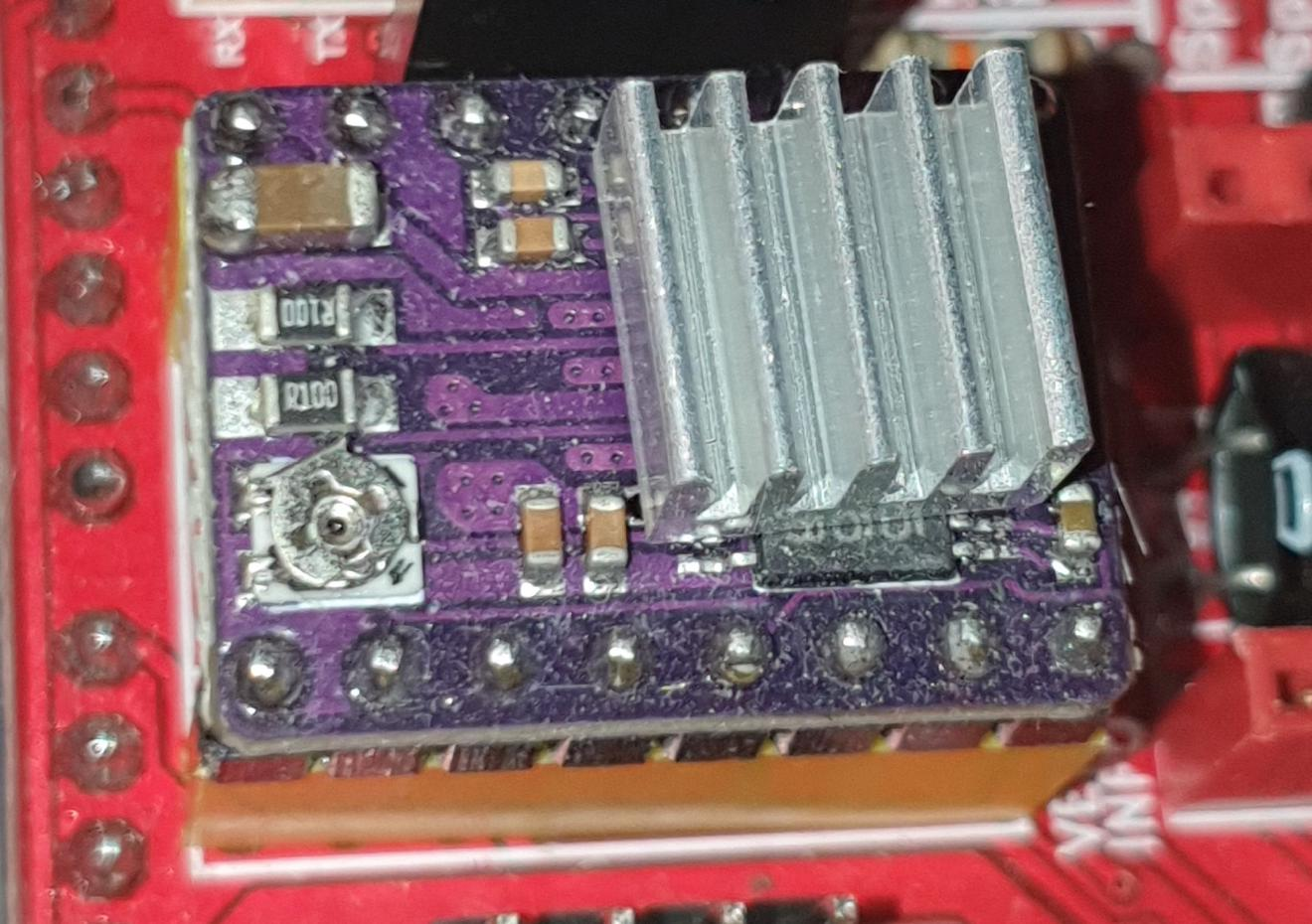
You usually have to buy stepper modules to plug into the CNC board that plugs into the Arduino. They come in two types. A slightly higher current version, marketed as HIGH CURRENT, and Slightly lower current version, marketed as HIGH CURRENT. I purchased the HIGH CURRENT version.
Power Supply
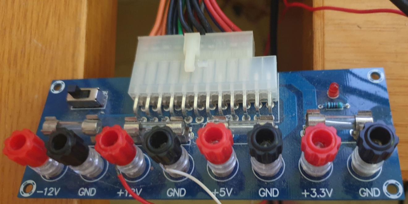
I use a PC power supply for testing. I have a nice break-out plate for it.
Housing and Lifter Design
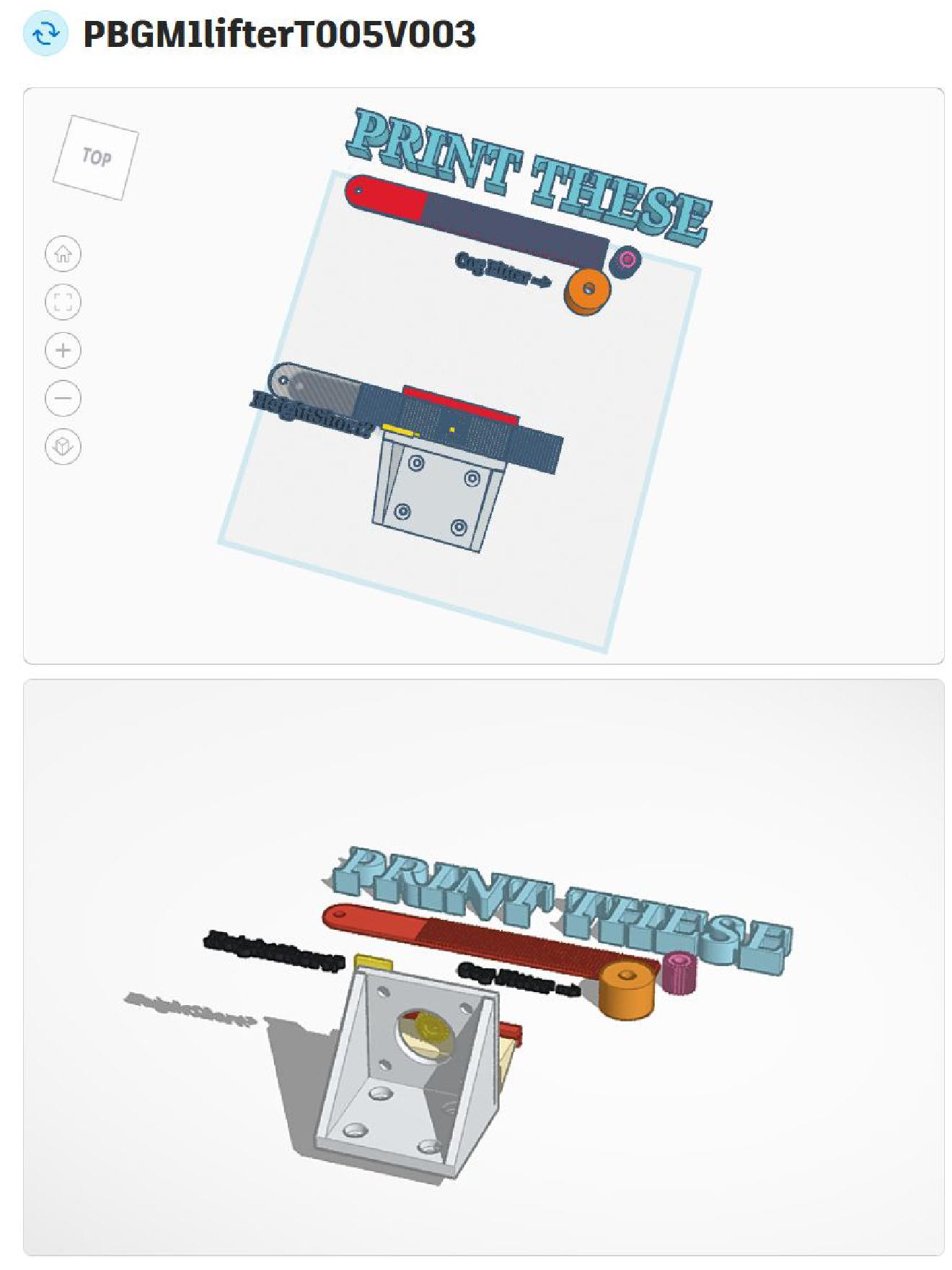
The first design was quite rough.
Printed
This is the final test piece - printed and mounted.
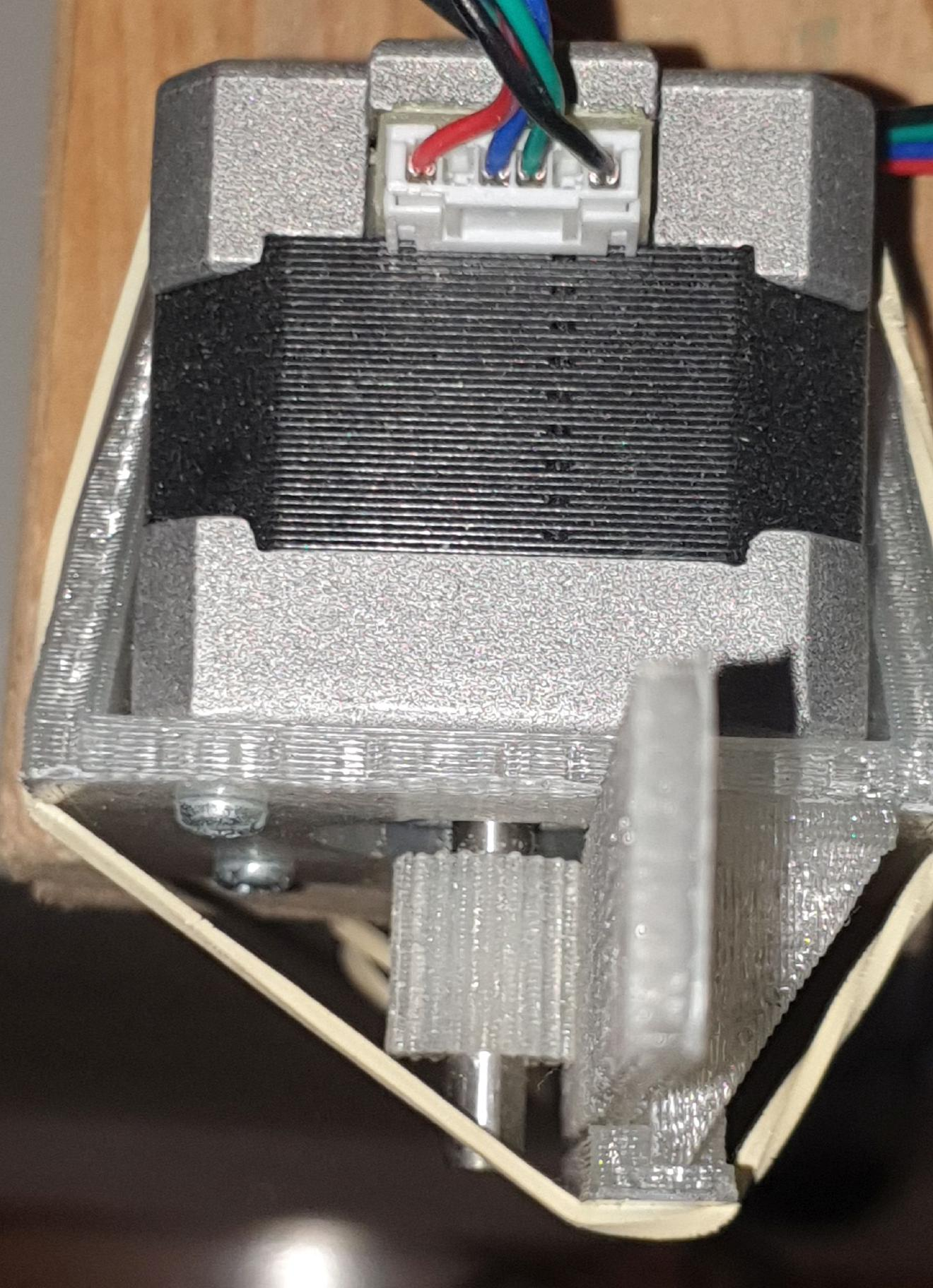
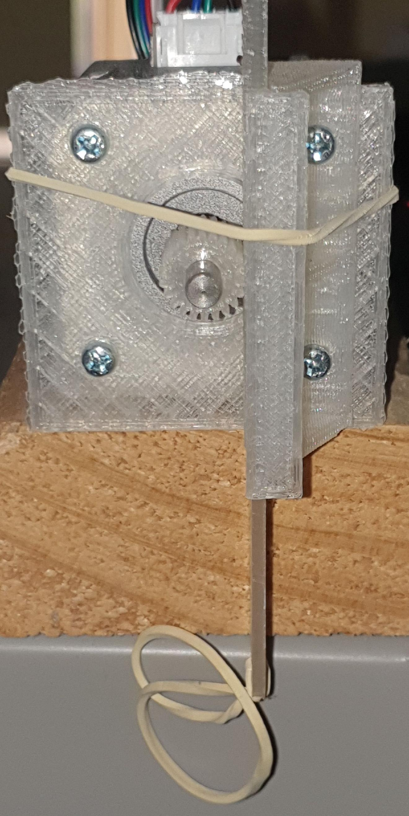
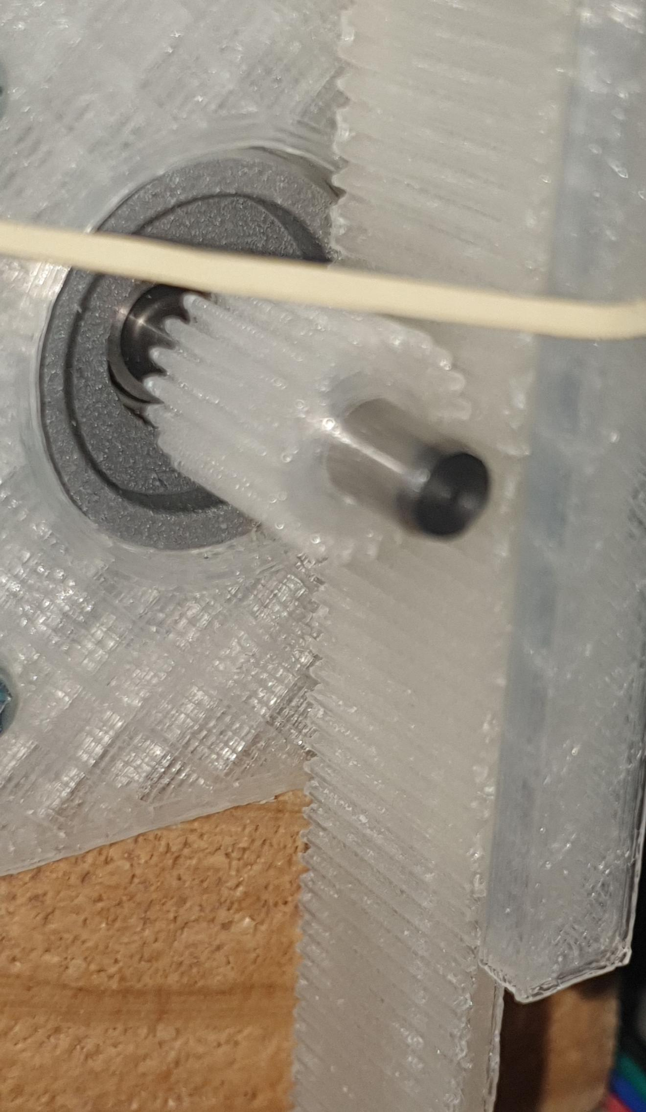
I used rubber bands as shock reducing couplings.
Setup and Testing
So the design works well. Initial testing with a screwdriver, then upgrading to 1.5Kg of water.
I like to give things a decent test; this one had a few thousand excursions with no signs of wear.
I called it a success and moved on.


