
Power Supply
The first thing you hear when you switch it on…
Table of Contents
I had a Gottlieb power supply:
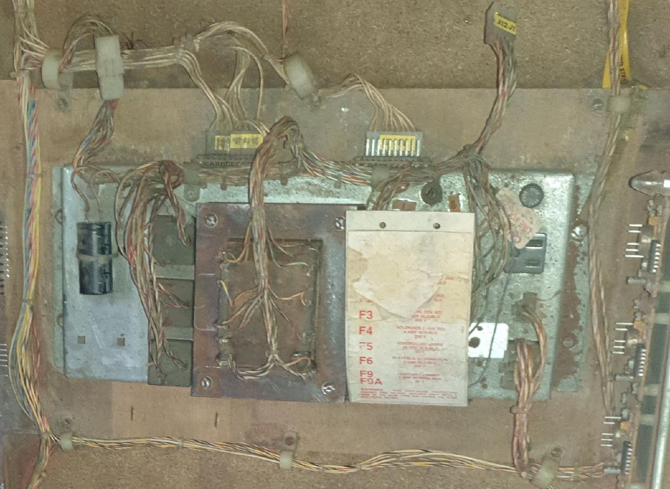
It had seen better days, but at least the wood it was on was only worm-eaten, and not rotten as well. I took it apart, gave it a good scrub and removed the rust, and put it back together again. While I was doing that I mapped out it’s connections, switch and transformer taps. When it was back together I measured some of it’s voltages. Then I put all the info into a spiffy table:
| Tap | Voltage | Type | Fuse | Actual Open Circuit Voltage | Connector | Id | Use |
|---|---|---|---|---|---|---|---|
| 5 | 6.2 | AC | F9 1A | ? | A12J2 | 122 | Display filament |
| 7 | Vco | AC | - | ? | A12J2 | 133 | Vco |
| 9 | 6.2R | AC | F9A 1A | ? | A12J2 | 144 | 6.2vac return |
| 1 | 32 | AC | F3 1/4A Slow | ? | A12J2 | 177 | 32vac |
| 2 | 32R | AC | - | ? | A12J2 | 111 | 32vac return |
| 3 | 12 | AC | F1 1/2A | ? | A12J2 | 655 | 12vac |
| 4 | 12R | AC | - | ? | A12J2 | 644 | 12vac return |
| 15 | 11 | AC | F2 6-1/4A Slow | ? | - | 211 | 11vac to rectifier |
| 16 | 11R | AC | - | ? | - | 244 | 11vac return` |
| - | 12 | DC | - | 13.3 | A12J2 | 200 | +12vdc |
| - | 0 | DC | - | 0 | 2A18J3 | 9 | Ground |
| 10 | 27 | AC | F4 8A Slow | ? | - | 266 | 27vac to rectifier |
| 11 | 27R | AC | - | ? | - | 288 | 27vac return |
| - | 24 | DC | - | 27.4 | A12J2 | 222 | +24vdc |
| - | 0 | DC | - | 0 | 2A18J3 | 9 | Ground |
| 12 | 6.3R | AC | - | ? | A12J2 | 000 | 6.3vac return |
| 13 | 6.3 | AC | F6 5A Slow | ? | A12J2 | 066 | 6.3vac |
| 14 | 8 | AC | F5 10A Slow | ? | 311 | 8vac to rectifier | |
| - | 6 | DC | - | 6.9 | A12J2 | 255 | 6vdc |
| - | 0 | DC | - | 0 | 2A18J3 | 9 | Ground |
I set about some testing and discovered some interesting things:
- It’s very heavy.
- It’s not a very efficient transformer, some energy lost in noise and heat.
- It makes a terrifying noise when turned on, as the windings and plates settle into place.
- Without line filters, it will happily reset every computer-device it can see.
Pretty much what you would expect.
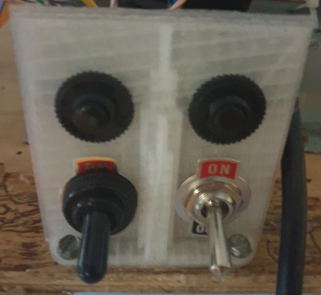
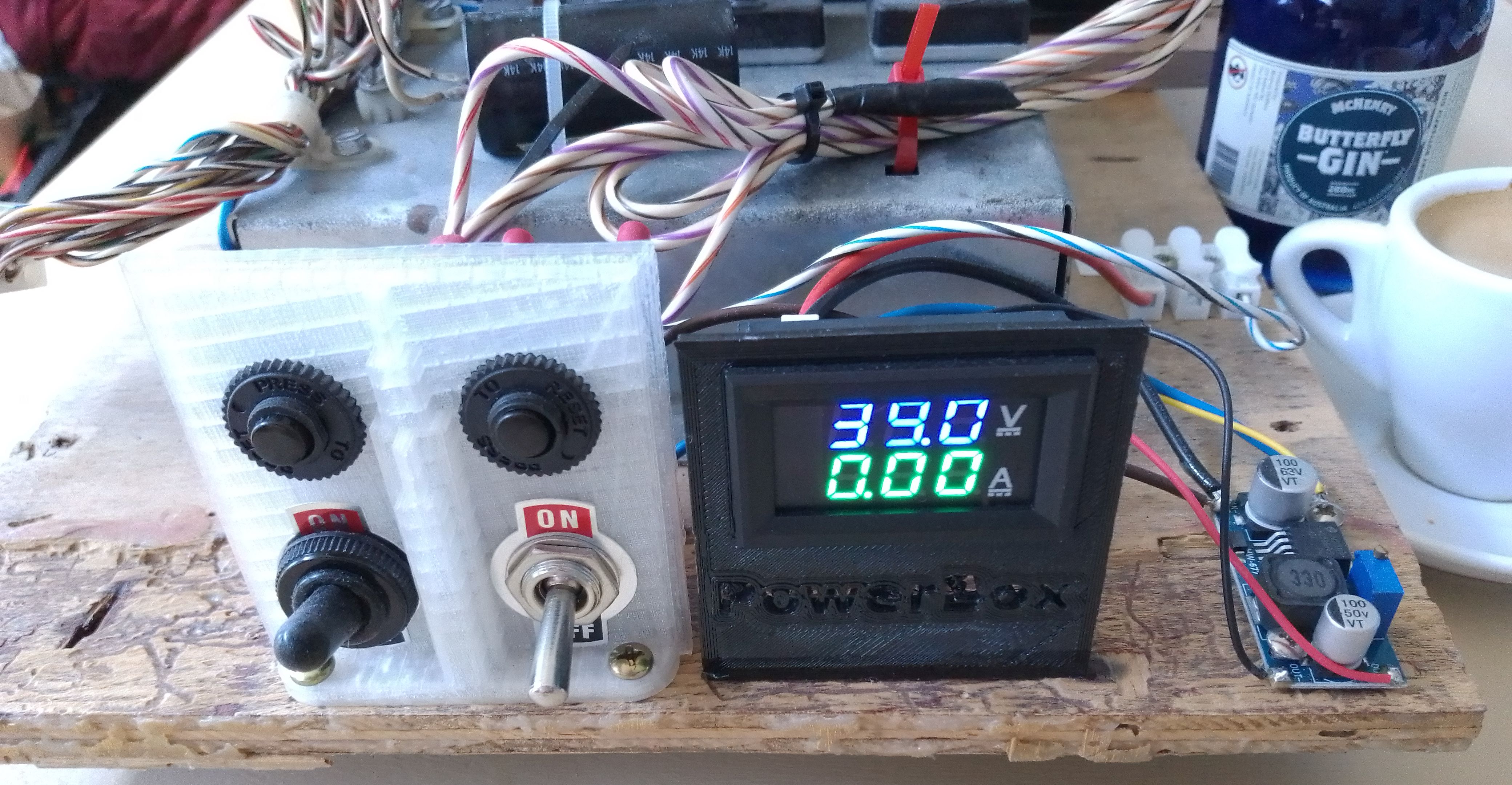
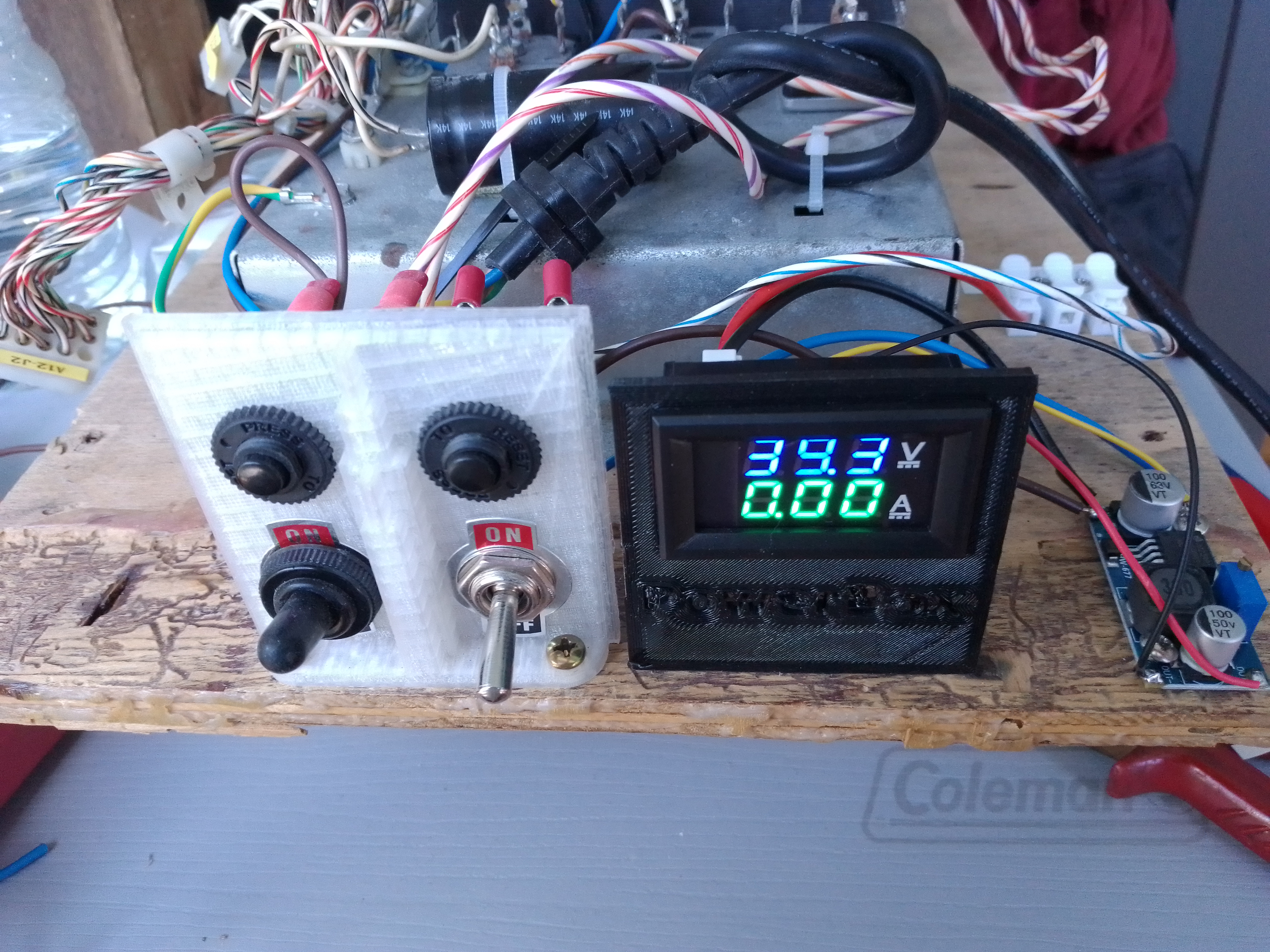
I made a nice switch-panel for it and switched the mains and 24V, adding a 3A circuit breaker to each. The existing fuse arrangement is untouched, the 3A breakers set testing limits. There is good, thick heat-shrink on all the connections. I designed a nice housing for the panel, but since it’s out of the way I didn’t print it. The final design will be different (more switches and breakers and some relays), so I will wait till then to make a fancy box.
Because I don’t want to disturb the wiring harness I took the 24VDC directly from the rectifier connections.
Transformer Unit Design
I have a fancy power-supply design for down the track. Don’t try and read it - it’s just for show.
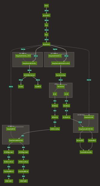
It includes monitoring of output voltage levels, temperature, and selective power (turns things on when they are needed).
Visual Current Limitation Device (VCLD)
Because I don’t like my coils burning up, I made a VCLD so I could see current inrush situations - where there is lots of initial current (like when solenoids are pulling in, or flippers before they are in hold position), AND a device to limit current after the inrush, since we should only need holding current.
The VCLD (yes I made the name up) is basically a halogen light bulb and a capacitor.
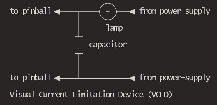
So, when the power-supply is turned on, the capacitor charges up, the lamp glows and fades out. When a coil fires, it sucks the charge out of the capacitor, and the lamp comes on hard as it tries to power the coil. For small coils it will do the job, for bigger coils there is enough current to hold the coil in, and that’s about it. When the coil goes into hold mode, the lamp dims as the capacitor is recharged. A dim glow remains, depending on how much hold current is being used.
Now this thing is no good for use with a running machine with lots of coils firing, but it is dandy for testing a newly wired up playfield. When I had a high impedance ground circuit, and my OPP and MPF were crashing. I used the VCLD to protect my drain coil while I worked out what was going on.
What values? Good question. 50w 24v bulb, and capacitor size big enough to pull in a coil.
Related posts
Power Supply #4
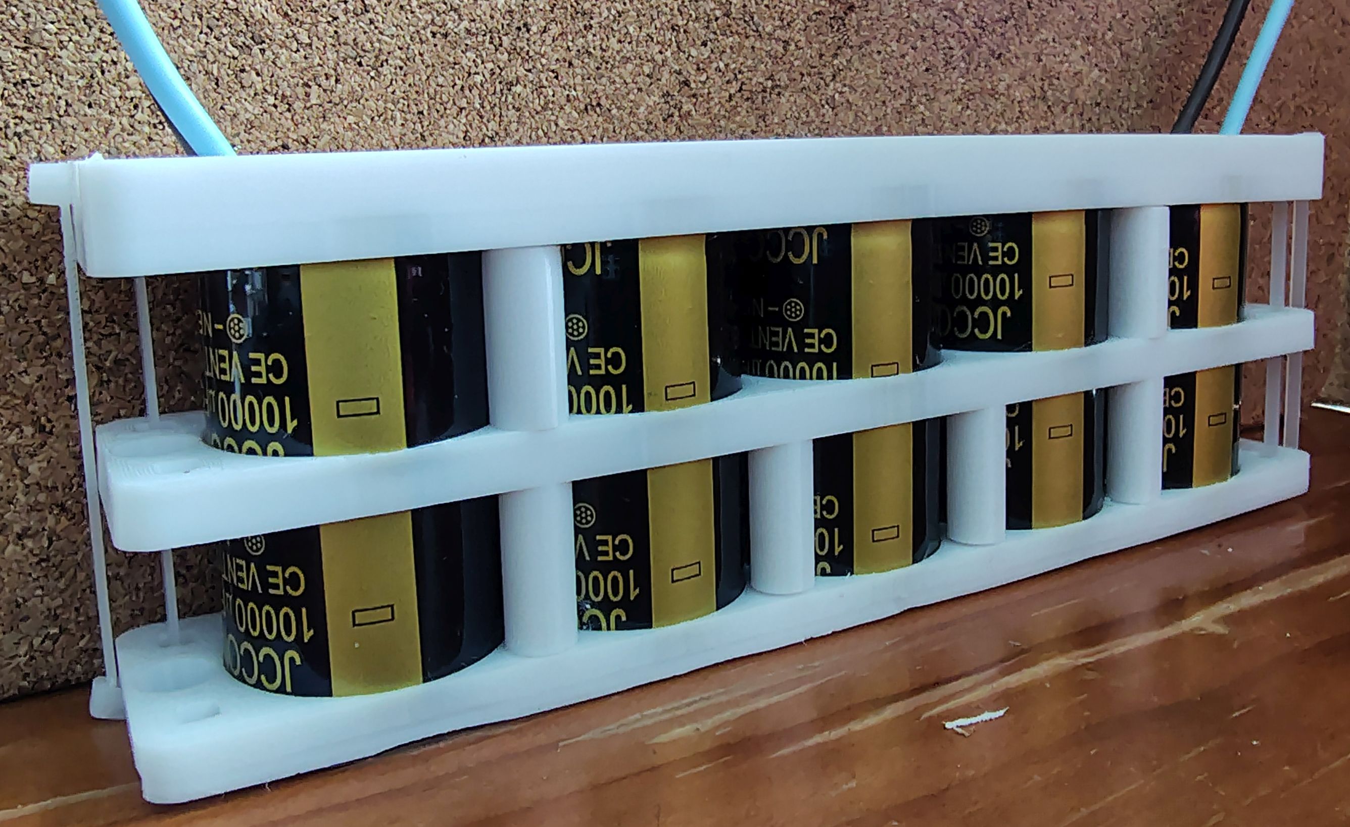
Capacitors So, even with a big beefy power transformer, and nice thick wires, you can never get enough current to a coil. Enter the Capacitor Caddy™. This fantastic device allows a bunch of reasonably priced Capacitors to be ganged up into a decent fast release energy store - just the thing for those pesky lethargic coils. The parts are 3D…
Power Supply #3
Final(?) assembly of my Gottleib Testing Power Supply What I wanted was a power supply that can give me lots of coil power and lighting power for 5Volt LEDs. What I got was everything except the 5Volt (I've not done the testing yet). I've been delayed doing this for ages - I wanted some furniture feet, big rubber stopper things…
Power Supply #2
Better is the Enemy of Done Words to live by. I've always hated napkin designs and quick sketches. They are ugly and confusing. There is no denying though, that they get the job done quick. The ugly schematic lead to a bit of ugly construction... So we have 240V switched with a circuit breaker, coil power switch, amp and volt…